Heat is the enemy.
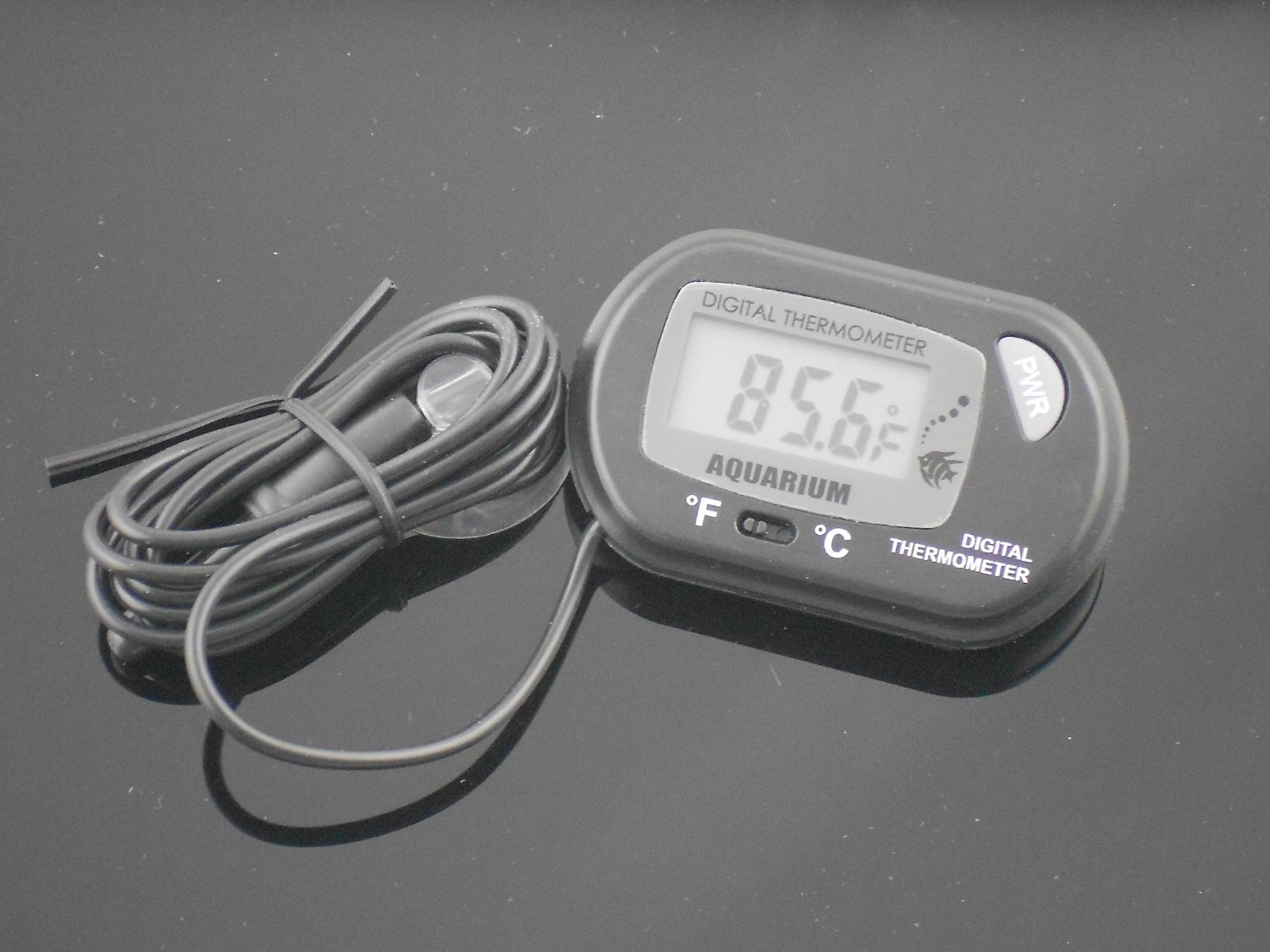
A $2 thermometer can save your $80 controller and a lot of headaches.
Electric motors can often take far more power put through them than their nominal rating, but over time the heat will build up and cause all sorts of problems. Mosfets can blow, phase wire insulation can melt, windings can fuse together. When the motor starts being under high torque load and the RPM speed is slow the electricity flowing through the windings mostly turns into waste heat. The best way to keep your BBS02 from blowing is to mount a much smaller 32-36T chainring on it. The 2nd best way to keep your controller from frying is to install a temperature sensor. It costs about $2 and takes about 7 minutes to do if the drive unit is not mounted yet and 15 minutes if the BBS02 is already mounted. Aquarium thermometers are available by hundreds of vendors on ebay right here.
The BBS02 comes with a temperature sensor that is supposed to shut down the drive unit before the mosfets are damaged. However the unit ships with a monstrous 48T chain-wheel which is way too big for trail-riding (even the smaller 44T is too big). Combine a chain-wheel that is far too large with mosfets which are way too cheap, then throw in a temp sensor which doesn’t cut in at a low enough temp and you have a recipe for disaster. If you neuter the power on the unit to 20 amps instead of 25 and lower the power to the throttle from 9 to 5 you can solve most of the problems your BBS02 would suffer in the hands of an inexperienced ebiker. However if it is your bike and you don’t want to loan it out the last thing you want to do is lower your power settings.

An aquarium thermometer from ebay, works for a long, long time even when you forget to turn it off after your ride. It even comes with a spare battery!
How To Do It
1) If unit is mounted to a bike already remove the drive side crank arm and chainwheel or chainwheel adapter. If your drive unit is not installed yet just skip this step.
2) Carefully remove the plastic reduction gear cover being careful to not lose the gasket or to get grease everywhere. This can be 5 or 7 screws depending on the unit

I usually wipe up the grease with a rag to keep it from getting everywhere. If you do this make sure to re-grease the gears before reassembly.
3) Remove the 3 bolts that hold the controller on. They tighten these bolts ridiculously tight and it’s not uncommon for me to strip them out. Use the right size wrench and then I suggest making sure the wrench is fully seated before you start to turn it. You can use a set of pliers to increase the torque but be careful because too much torque and it will strip. If you strip it remove it with an EZout adapter and a power drill.

Be extremely careful on this step to not strip out the hex bolts.
4) Remove the controller by carefully rocking it back and forth and pulling it away from the unit. The cables are often siliconed to the base and they often pop free when pulling the controller away.

You can see the PAS disabled by removing the grey wire from the pin block in the center and on the bottom left the temp probe laid down against the potting material ready to be siliconed in.
5) This is the perfect opportunity to disable the PAS system if you want to. Pull the small 4 pin connector apart and remove the grey wire from the female side of the plug and cover it in electrical tape and put the connector back together. This will completely disable the Pedal Assist system but will also give your throttle several levels of power settings (depending on how your controller is programmed).

6) Clip off suction cups.

Carefully push the probe through the rubber gasket.
7) Pull the rubber square with the wires running though it and carefully push the probe through between the larger wires.

Find a good spot for the probe where the controller can still close properly.
8) Position the probe with the tip closer to the outside of the case (this is where the mosfets are). Put the controller back on and make sure it can close properly before using the silicone.

9) Silicone the probe in place using silicone which will work as a heat-transfer medium. Cover the probe completely in silicone then carefully put the controller back in place while the silicone is still wet. Replace the three screws on the controller then the plastic cover with the 5 or 7 screws. Make sure to not over-tighten the black cover as it breaks VERY easily.

10) Mount the sensor on the top tube near the front of the bike. Be sure to route the cables so that when you bash the drive unit on logs it will not eat through the wire.
The temp probe will give different temps on different bikes depending on where it ended up getting placed but a good rule of thumb I use is –
- 140F + Stop riding and let it cool
- 130F + Don’t use full throttle, only half throttle
- 120F + Take it easy
- 110F or less go whole hog
The temps you are reading are controller temps and not motor temps. It takes time for the motor heat to make it’s way into the controller housing, so keep that in mind when riding. The cheap mosfets create plenty of heat on their own, especially when they are overloaded and the motor is not spinning fast. Just installing a temp sensor is not enough. You also need to use a smaller chain-wheel for trail-riding. I recommend a 32-36T ring with 34T being my personal favorite.
Ride On.